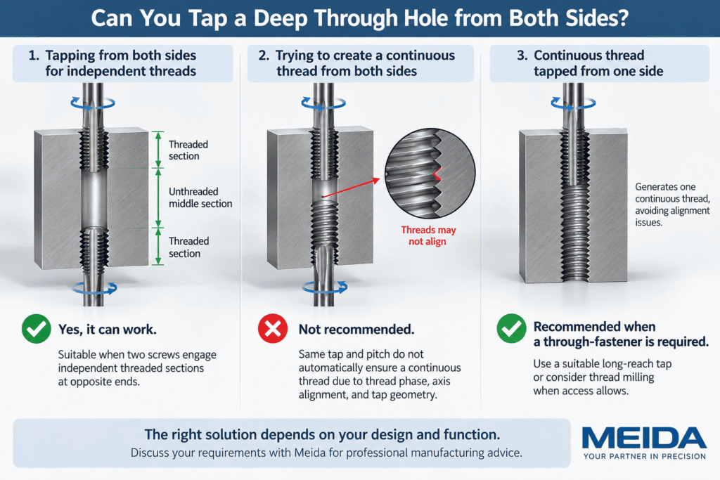
When a through hole is too deep for a standard tap, machining halfway from each end may seem like a practical solution. However, the most important question is not simply whether the tool can reach the required depth. It is whether the finished component needs two independent threaded sections or one continuous internal thread.
Tapping a hole from both sides can be appropriate for separate threaded sections. However, independently tapping halfway from each end does not automatically produce a continuous thread. This distinction follows from thread geometry: matching the diameter and pitch does not necessarily make two separately generated helices line up.
For engineers and buyers, understanding this difference helps define the right machining and inspection requirements before a part is quoted.
This article focuses on straight internal screw threads, such as metric and Unified threads.
When Is Tapping From Both Sides Appropriate?
Consider an illustrative component that is 60 mm thick. It has a drilled through hole, but the assembly only requires a short screw to enter each end.
If the drawing specifies independent threaded sections, the supplier can evaluate tapping from both faces. Neither screw needs to travel through the middle or engage the opposite threaded section.
That is a different requirement from a long threaded rod that must screw through the entire component.
The following decision guide is based on that functional distinction:
| Assembly requirement | Implication for two-sided tapping |
|---|---|
| Two separate screws engage independent threaded sections at opposite ends. | Two-sided tapping can be suitable, subject to the specified depths, tolerances, and assembly requirements. |
| One bolt or threaded rod must screw through the full length. | Do not assume independently tapped sections will form a continuous thread. A validated matching process is necessary. |
| One rod simultaneously engages two threaded sections separated by a clearance region. | The sections still need compatible helical alignment. A clearance region alone does not solve a thread-phase mismatch. |
The key engineering question is:
Will each threaded section work independently, or must one fastener engage both sections together?
A hole being open at both ends does not, by itself, answer that question. The drawing and assembly requirements must do so.
Why Two Half-Depth Threads May Not Match
Matching Pitch Does Not Guarantee Matching Thread Phase
An internal thread follows a helical path. For two independently machined sections to function as one continuous thread, their geometry must match at the transition—not just their nominal size.
The angular position of the helix relative to its axial position is often described as thread phase. Two threads can share the same diameter, pitch, and handedness but still have different starting positions.
For illustration, a single-start M8 × 1.25 thread advances 1.25 mm per revolution. A 90-degree phase difference corresponds geometrically to an axial offset of:
1.25 × 90 ÷ 360 = 0.3125 mm
This is an illustrative calculation, not an allowable manufacturing error. It demonstrates why using the same thread specification does not automatically make two thread starts compatible. The calculation follows the single-start relationship between lead, pitch, and rotation.
Using the same tap on both sides does not, by itself, preserve the relationship between the tool’s angular position and its axial starting point. Therefore, the engineering conclusion is that “same tap, same pitch” is not sufficient evidence of thread continuity.
The Thread Axes Must Also Match
Thread phase is only one part of the problem.
Geometrically, a continuous thread must follow the intended axis as well as the intended helix. When the component is repositioned, the second operation must maintain the required positional and angular relationship to the first.
Consequently, a process review should address both axis alignment and helical alignment. Controlling only one does not establish that the two sections will function together.
Tap-Tip Depth Is Not Full-Thread Depth
The front of a tap has a chamfered cutting section. Its teeth progressively generate the thread profile, so the tap tip reaches farther than the last fully formed thread.
This means that advancing the tap tip halfway into a component from each face does not necessarily create full-profile threads all the way to the center. The chamfer geometry must be included in the depth calculation.
Extending the cuts until they overlap is not a substitute for controlling thread phase. The process must establish a compatible thread path as well as sufficient full-form depth.
How Should Deep Through Holes Be Threaded?
A useful starting point is to separate component thickness, tool reach, and required thread depth.
For example, a 60 mm-thick component with a 12 mm threaded section at each end has a different threading requirement from a component needing 60 mm of continuous thread. These are illustrative dimensions, not recommended engagement lengths.
Tool selection must then follow the actual application. Tapping tools have application-specific geometry and depth capabilities; a depth rating for one tap family is not a universal limit for every material or threading process.
Evaluate a Suitable Tap From One Side
Where access and tooling permit, generating the continuous thread from one side avoids introducing an independently started junction.
The review should consider usable reach, shank clearance, chamfer allowance, lubrication, and the chip-exit path—not just the tool’s overall length. Tap geometry and coating should also match the material and hole configuration.
For appropriate through-hole applications, spiral-point taps push chips forward. That makes the available space ahead of the tap and the exit condition important parts of the setup. A physically open hole still needs an effective chip-removal path.
Consider Thread Milling Where Access Allows
Thread milling is an alternative worth evaluating when conventional tapping is difficult.
It produces smaller chips and allows thread-size adjustments through tool offsets. These features can help with chip management and dimensional control. However, cutter selection still depends on the required thread geometry and available reach.
Thread milling is not an unlimited-depth solution. Long tool overhang, insufficient rigidity, runout, and poor chip evacuation can affect the process. Sandvik Coromant’s troubleshooting guidance specifically identifies these factors as areas to control.
Review Whether Full-Length Threading Is Necessary
Before specifying a difficult continuous thread, ask the design engineer to confirm how much engagement the assembly actually needs.
For separate fasteners entering from opposite ends, independent threaded sections may satisfy the design. For a through-fastener, an alternative arrangement—such as a clearance section and one threaded engagement zone—may be worth evaluating.
These are design-review options, not automatic substitutions. Required loads, materials, assembly access, and the released drawing must govern the decision.
How to Specify Two-Sided Threads on a Drawing
A drawing should clearly distinguish between a drilled through hole and a thread that must function continuously through the component.
For quotation and manufacturing review, provide three groups of information:
- Thread definition: Size, pitch, handedness, tolerance class, and applicable acceptance requirements.
- Geometry: Full-form thread depth from each reference face, central bore dimensions, entry chamfers, and permitted thread runout.
- Function: Whether the sections are independent or whether one fastener must engage both.
The following notes illustrate the difference. They are not complete drawing specifications or strength recommendations.
Example: independent threaded sections
M8 × 1.25–6H. Minimum 12 mm full-form thread depth from Face A and Face B. Threaded sections function independently. Central bore and thread runout as detailed.
Example: a continuous through-thread
M8 × 1.25–6H THRU. Continuous functional thread required throughout the specified length, including any transition between machining operations.
The first example permits an evaluation of separate end-threading operations. The second establishes a functional requirement that cannot be satisfied merely by showing that a screw enters each end.
Full-form thread depth should not be confused with tap-tip travel because the chamfered portion does not immediately generate the complete profile.
Do not replace a continuous through-thread with two independent threaded sections without design approval.
How Should Deep Threaded Holes Be Inspected?
Inspection must reflect the thread’s intended function.
For independent end threads, verify each section’s specified size and usable depth. For a continuous thread, the inspection plan must also cover the internal transition and the required length—not just the entrances.
GO and NO-GO thread gages perform different functions. A GO gage assesses functional thread fit, while NO-GO acceptance depends on the applicable standard and conditions. Gages should not be forced into the workpiece.
A practical consequence is that a short GO plug entering each end does not demonstrate the condition of an unreachable middle section. For a long engagement, agree on suitable gage reach and any additional functional verification with the customer or gage specialist.
A mating-bolt test can supplement that inspection, but it does not, on its own, establish compliance with the specified thread tolerance. Dimensional acceptance should remain tied to the appropriate gaging method and drawing requirements.
Frequently Asked Questions
Can a deep through hole always be tapped halfway from each end?
No. That approach can be considered for independent threaded sections, but it does not automatically produce one continuous thread. The engineering limitation is the need to match the helical path, not simply the nominal pitch.
Does tapping from both sides automatically reduce manufacturing cost?
Not necessarily. In a cost comparison, any benefit from shorter tool access should be weighed against the second setup, alignment work, inspection, and possible rework. Compare the complete manufacturing route rather than assuming that two shorter cuts are cheaper.
Is thread milling always better for deep threads?
No. Thread milling offers chip-management and size-adjustment advantages, but usable reach and process stability still matter. The choice should follow the actual hole geometry, material, tooling, and inspection requirements.
Discuss Your Threaded Part With Meida
Meida provides custom metal fabrication, machining, and design-for-manufacturing support, including reviews of manufacturability, tolerances, and potential cost reductions.
For a component with deep threaded holes, send your 2D drawing, available 3D model, material specification, and assembly requirements. Please identify whether the hole needs separate threaded sections or a continuous through-thread.
Start with what the fastener must do. Then select the machining process and inspection method to match.