
In precision sheet metal fabrication, many of the most important cost decisions are made before production begins.
A part may look perfect in a CAD model, but unnecessary tolerances, inconsistent bend radii, or poorly positioned holes can make it more difficult—and more expensive—to manufacture. These small design choices often result in additional tooling, slower production, higher scrap rates, and costly secondary operations.
At Meida, our engineers review designs from a manufacturing perspective to identify opportunities for simplification. Here are four practical Design for Manufacturability—or DFM—recommendations that can help reduce sheet metal fabrication costs without compromising performance.
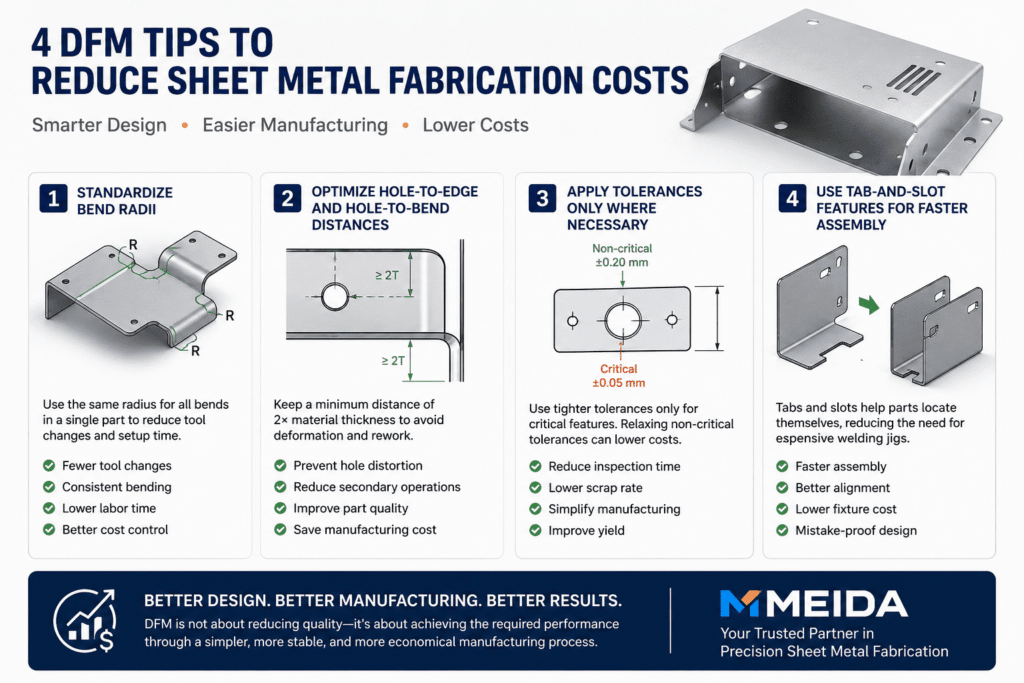
1. Standardize Bend Radii
Using multiple bend radii in a single sheet metal part may require different press brake tools and additional machine setup.
Every tooling change adds production time. For small batches, this extra setup can have a noticeable impact on the unit price. For larger production runs, even minor inefficiencies can accumulate into significant costs.
Whenever the design allows, use a consistent bend radius throughout the part. A standardized bend radius can:
- Reduce press brake tooling changes
- Simplify production setup
- Improve bend consistency
- Shorten manufacturing lead times
- Lower overall fabrication costs
The ideal bend radius depends on the material type, material thickness, bending method, and required part performance. Discussing these factors with your sheet metal manufacturer early in the design process can prevent unnecessary revisions later.
2. Optimize Hole-to-Bend and Hole-to-Edge Distances
Holes, slots, and cutouts placed too close to a bend line may stretch or deform during bending.
This can lead to oval-shaped holes, dimensional inaccuracies, cracking, or the need for manual correction after forming. In some cases, the feature must be machined in a separate operation, adding both cost and lead time.
As a general starting point, maintain sufficient clearance between a hole and the nearby bend or edge. A minimum distance of approximately two times the material thickness may be suitable for some applications, but the actual requirement can also depend on:
- Bend radius
- Hole diameter
- Material properties
- Grain direction
- Forming method
For best results, critical hole locations should be reviewed by the fabrication team before the drawing is released for production.
3. Apply Tight Tolerances Only Where Necessary
Does every dimension on a mounting bracket really need a tolerance of ±0.05 mm?
Tight tolerances may require more precise machinery, additional inspections, slower processing, and secondary machining. They can also increase the risk of rejected parts, even when the rejected dimensions have little effect on the final assembly.
A better approach is to divide dimensions into two categories:
Critical dimensions directly affect fit, alignment, sealing, safety, or functional performance.
Non-critical dimensions have limited influence on how the part functions or assembles.
Where appropriate, relaxing a non-critical tolerance from ±0.05 mm to ±0.2 mm can help:
- Reduce inspection requirements
- Improve production yield
- Lower scrap rates
- Eliminate unnecessary machining
- Reduce the unit price
Tolerances should reflect the functional needs of the part—not simply the maximum precision available from the manufacturing process.
4. Use Tab-and-Slot Features for Faster Assembly
Welded assemblies often require fixtures or jigs to hold components in the correct position.
Custom welding fixtures can increase upfront costs, especially for prototypes and low-volume production. They also add preparation time before welding can begin.
Adding simple tab-and-slot features allows mating parts to locate themselves during assembly. This design approach can improve positioning and reduce reliance on complex fixtures.
Well-designed tabs and slots can:
- Speed up assembly
- Improve repeatability
- Reduce welding jig costs
- Minimize alignment errors
- Simplify operator training
- Support mistake-proof assembly
Clearances should still be designed according to the cutting process, material thickness, coating requirements, and desired fit. Slots that are too tight may make assembly difficult, while excessive clearance may reduce positioning accuracy.
Better Designs Create Better Manufacturing Results
DFM is not about reducing quality. It is about achieving the required performance through a simpler, more stable, and more economical manufacturing process.
By standardizing bend radii, improving feature placement, applying realistic tolerances, and incorporating self-locating assembly features, engineering teams can reduce manufacturing complexity before it reaches the production floor.
The earlier these issues are identified, the easier—and less expensive—they are to correct.
Consult Meida Before Finalizing Your Design
Working with Meida during the design stage can help you identify potential manufacturing risks, avoid unnecessary secondary operations, and select more cost-effective production methods.
Whether you are developing a prototype or preparing for volume production, our engineering team can provide practical DFM feedback based on your material, geometry, tolerance, and assembly requirements.
Send us your drawings for a DFM review and discover how small design changes can improve quality, shorten lead times, and protect your manufacturing budget.